1D parallel plate discharge
Parallel plate discharge in argon using dual frequency excitation
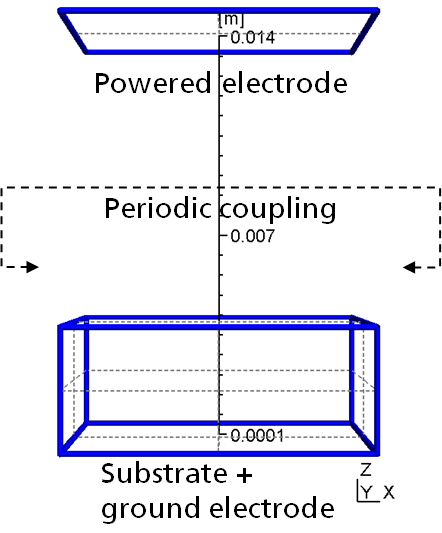
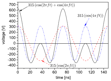
We validated our PIC-MC implementation with that from Donko081 by comparing our results for a 1d3v simulated parallel plate discharge in argon. Hereby a dual frequency excitation is applied, i.e. a 13.56 MHz and a 27.12 MHz cosine signal is superposed with an amplitude of 315 volts.
| Parameter | Setting | Unit |
|---|---|---|
| Argon pressure | 0.2 | [Torr] |
| Amplitude | 315 | [V] |
| Frequency | 13.56 + 27.12 | [MHz] |
| Electrode distance | 6.5 | [cm] |
| Electron time step | 1e-11 | [s] |
| Cell spacing | 1 x 1 x 1 | [mm3 ] |
| Charge weighting | 1e6 | [-] |
| Secondary electron yield | 0.2 (> 0.1 to approximate electron reflection) | [-] |
| Electron reflection on wall | None | [-] |
| Electron energy partitioning | one-takes-it-all | [-] |
Table 1: PIC-MC settings and simulation parameters used for the dual frequency discharge.
The results are nearly identical for both PIC-MC implementations, like seen for example in the ar+ hit histogram on the powered and grounded electrode, respectively. However, we had some discrepancies at first as we used a more simplified ar+ collision model as in Donko08. Thus, we adjusted our model to that of Donko08 using the more sophisticated ar+ collision model from Phelps.
| Ar+ histogram from Donko08 | Ar+ histogram from IST | Ar+ histogram from IST using simplified ar+ collision scheme |
|---|---|---|
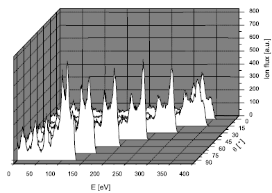 | 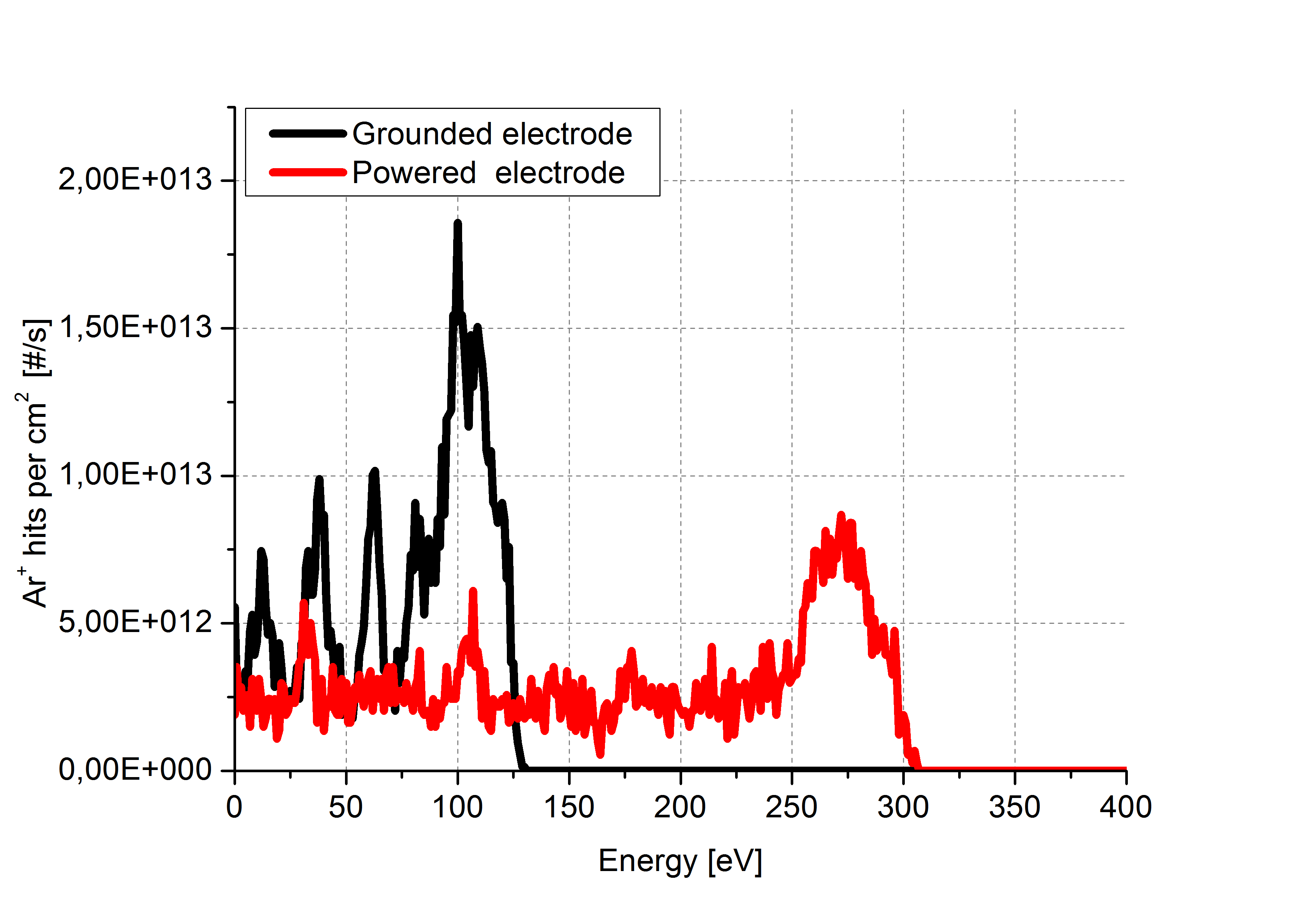 | 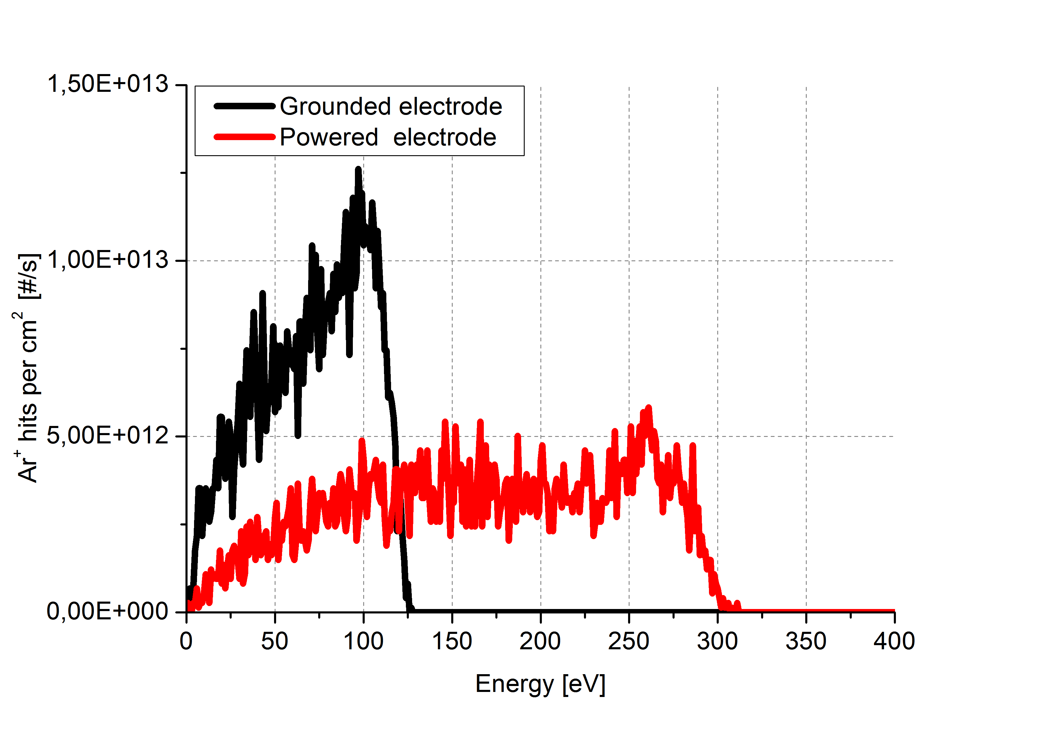 |
Figure 2: Ar+ hit histogram for different PIC-MC implementations and ar+ collision models, respectively.